
Multi-Area OSPF in GNS3: A Cisco + Juniper Multivendor Lab
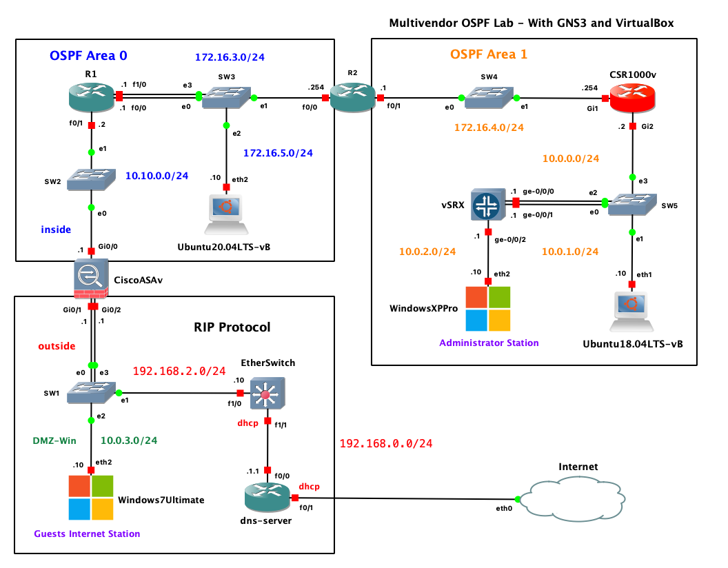
Build a multi-area OSPF network in GNS3 across three network operating systems — Cisco IOS, IOS-XE and Juniper Junos. Area 0 backbone, an ABR, the multivendor gotchas that break adjacency, and the show commands that prove it works.
Why build an OSPF lab?
OSPF is one of the most common interior gateway protocols in enterprise networks. Reading about it is useful, but actually seeing adjacencies form, LSAs propagate, and routes appear in the table is where the protocol starts to make sense.
A small virtual lab built with GNS3 and VirtualBox gives you a safe place to practice:
- Router deployment and interface addressing
- OSPF neighbor formation
- Single-area and multi-area designs
- Route advertisement and path selection
- Troubleshooting mismatched settings
This setup is also ideal for students preparing for networking exams, engineers brushing up on routing fundamentals, and anyone building a home lab without dedicated hardware.
Lab goals
In this post, the objective is to build a simple but useful OSPF environment using:
- GNS3 for topology design and packet-level network emulation
- VirtualBox for hosting virtual machines or router images, depending on your lab design
- A few routers connected in a small topology
- Optional Linux hosts for ping, traceroute, and packet capture tests
By the end, you should have a working lab where routers exchange routes dynamically using OSPF.
What you need
Before starting, make sure the following components are installed.
Software
- GNS3
- GNS3 VM (recommended for better performance)
- Oracle VirtualBox
- A router image supported in your environment
- Optional Linux VM, such as:
- Ubuntu Server
- TinyCore Linux
- Alpine Linux
Host requirements
A modern laptop or desktop is usually enough for a small lab. More RAM helps significantly.
Recommended minimums:
- 4 CPU cores
- 8 GB RAM
- 20+ GB free disk space
More comfortable for larger labs:
- 16 GB RAM or more
- SSD storage
- Hardware virtualization enabled in BIOS/UEFI
Understanding the role of GNS3 and VirtualBox
A common point of confusion is how these tools fit together.
GNS3
GNS3 is the network lab platform. It lets you:
- Drag and drop routers, switches, and endpoints
- Connect devices with virtual links
- Start captures with Wireshark
- Test topologies without physical hardware
VirtualBox
VirtualBox is the hypervisor. It runs virtual machines that can be attached to your GNS3 topology.
Examples include:
- Linux clients used for testing connectivity
- Network appliances packaged as VMs
- In some workflows, the GNS3 VM itself
In short:
- GNS3 builds the network
- VirtualBox runs supporting virtual machines
Suggested lab topology
A simple three-router OSPF lab is a great starting point.
        10.0.12.0/30              10.0.23.0/30
   R1 ---------------- R2 ---------------- R3
    |                                          |
    |                                          |
192.168.1.0/24                            192.168.3.0/24
 Host-A                                    Host-B
Example addressing plan
| Device | Interface | IP Address | Notes |
|---|---|---|---|
| R1 | G0/0 | 10.0.12.1/30 | Link to R2 |
| R2 | G0/0 | 10.0.12.2/30 | Link to R1 |
| R2 | G0/1 | 10.0.23.1/30 | Link to R3 |
| R3 | G0/0 | 10.0.23.2/30 | Link to R2 |
| R1 | G0/1 | 192.168.1.1/24 | LAN for Host-A |
| R3 | G0/1 | 192.168.3.1/24 | LAN for Host-B |
| Host-A | eth0 | 192.168.1.10/24 | GW 192.168.1.1 |
| Host-B | eth0 | 192.168.3.10/24 | GW 192.168.3.1 |
For the first lab, place everything in OSPF Area 0.
Installing GNS3 and VirtualBox
Exact installation steps vary by operating system, but the high-level process is straightforward.
1. Install VirtualBox
Download and install VirtualBox from Oracle. During installation:
- Accept host network adapter prompts
- Allow required kernel or driver components
- Reboot if prompted
2. Install GNS3
Install the GNS3 GUI and related components. If prompted, enable:
- Wireshark integration
- Npcap/WinPcap support on Windows
- GNS3 VM support if you plan to use it
3. Import or configure the GNS3 VM
Using the GNS3 VM is often the smoothest option, especially for appliance-based labs.
General steps:
- Import the GNS3 VM into VirtualBox
- Start the VM
- Open GNS3
- Go to preferences and enable the GNS3 VM
- Verify that the local GUI can talk to the VM backend
Connecting VirtualBox to GNS3
Once VirtualBox is working, you can add VirtualBox VMs to your GNS3 projects.
Typical workflow:
- Create a VM in VirtualBox
- Install a lightweight OS if needed
- In GNS3, add a new VirtualBox VM template
- Map the correct network adapters
- Drag the VM into the topology
This is useful for adding:
- Client hosts
- DNS or web servers
- Attack/defense test systems
- Monitoring boxes
Creating the OSPF lab in GNS3
Now build the topology.
Step 1: Create a new project
In GNS3:
- Click New Project
- Give it a name such as
ospf-lab - Save it
Step 2: Add routers
Drag three routers into the workspace:
- R1
- R2
- R3
The exact router type depends on the images you have available. Common options include:
- Cisco IOSv
- Cisco IOU/IOL
- VyOS
- FRRouting-based appliances
Step 3: Add test hosts
Optionally add two lightweight Linux VMs:
- Host-A connected to R1
- Host-B connected to R3
If you do not want full VMs, GNS3’s built-in VPCS nodes are often enough for ping testing.
Step 4: Wire the topology
Connect:
- R1 to R2
- R2 to R3
- Host-A to R1
- Host-B to R3
Step 5: Start devices
Boot all routers and hosts, then open consoles.
Base IP configuration
Before enabling OSPF, configure interfaces and verify Layer 3 connectivity on directly connected links.
Below is a Cisco-style example.
R1
enable
configure terminal
hostname R1

interface g0/0
 ip address 10.0.12.1 255.255.255.252
 no shutdown

interface g0/1
 ip address 192.168.1.1 255.255.255.0
 no shutdown

end
write memory
R2
enable
configure terminal
hostname R2

interface g0/0
 ip address 10.0.12.2 255.255.255.252
 no shutdown

interface g0/1
 ip address 10.0.23.1 255.255.255.252
 no shutdown

end
write memory
R3
enable
configure terminal
hostname R3

interface g0/0
 ip address 10.0.23.2 255.255.255.252
 no shutdown

interface g0/1
 ip address 192.168.3.1 255.255.255.0
 no shutdown

end
write memory
Host addressing
For Linux hosts:
# Host-A
ip addr add 192.168.1.10/24 dev eth0
ip route add default via 192.168.1.1

# Host-B
ip addr add 192.168.3.10/24 dev eth0
ip route add default via 192.168.3.1
If you use VPCS instead:
# Host-A
ip 192.168.1.10/24 192.168.1.1

# Host-B
ip 192.168.3.10/24 192.168.3.1
Verifying the underlay before OSPF
Always check the basics first.
From R1, test reachability to R2:
ping 10.0.12.2
From R3, test reachability to R2:
ping 10.0.23.1
At this stage:
- Directly connected interfaces should ping successfully
- End-to-end LAN reachability will not work yet
- The routing table should only show connected routes
Useful command:
show ip route
Enabling OSPF
With IP connectivity in place, enable OSPF on all routers.
OSPF design for this lab
- Process ID:
1 - Area:
0 - All links in backbone area for simplicity
R1 OSPF config
configure terminal
router ospf 1
 router-id 1.1.1.1
 network 10.0.12.0 0.0.0.3 area 0
 network 192.168.1.0 0.0.0.255 area 0
end
write memory
R2 OSPF config
configure terminal
router ospf 1
 router-id 2.2.2.2
 network 10.0.12.0 0.0.0.3 area 0
 network 10.0.23.0 0.0.0.3 area 0
end
write memory
R3 OSPF config
configure terminal
router ospf 1
 router-id 3.3.3.3
 network 10.0.23.0 0.0.0.3 area 0
 network 192.168.3.0 0.0.0.255 area 0
end
write memory
Checking neighbor adjacency
Once OSPF is configured, routers should begin exchanging hello packets and forming adjacencies.
Run:
show ip ospf neighbor
Expected result:
- R1 should see R2
- R2 should see R1 and R3
- R3 should see R2
If all is well, neighbor states should reach FULL.
Checking learned routes
After adjacency forms, verify that routes appear in the routing table.
show ip route ospf
You should see:
- R1 learning
192.168.3.0/24 - R3 learning
192.168.1.0/24 - R2 learning both LANs as OSPF routes if not directly connected
A full route table view is also useful:
show ip route
Look for routes marked with O, which indicates OSPF.
End-to-end testing
Now test from one host to the other.
From Host-A:
ping 192.168.3.10
Then run a traceroute if available:
traceroute 192.168.3.10
Expected path:
- Host-A
- R1
- R2
- R3
- Host-B
If the ping succeeds, your OSPF lab is functioning.
Useful troubleshooting commands
OSPF labs are great because they fail in realistic ways. These commands help isolate issues quickly.
Interface and IP status
show ip interface brief
show interfaces
OSPF process and interface details
show ip ospf
show ip ospf interface
show ip protocols
Neighbor and database checks
show ip ospf neighbor
show ip ospf database
Routing verification
show ip route
show ip route ospf
Connectivity checks
ping <destination>
traceroute <destination>
Common OSPF issues in a virtual lab
When OSPF does not come up, the root cause is often simple.
1. Interfaces are shutdown
Symptom:
- No neighbor adjacency
- No pings on directly connected links
Fix:
- Check
show ip interface brief - Apply
no shutdown
2. Wrong IP subnet or mask
Symptom:
- Direct ping fails
- Interfaces look up but cannot communicate
Fix:
- Verify both ends of each link are in the same subnet
- Confirm masks match the design
3. OSPF network statement mismatch
Symptom:
- Interfaces have IP addresses
- OSPF process is running
- No adjacency forms on expected links
Fix:
- Check wildcard masks
- Confirm the interface networks are actually included in OSPF
Example:
network 10.0.12.0 0.0.0.3 area 0
4. Area mismatch
Symptom:
- Hello packets exchanged
- Adjacency does not fully form
Fix:
- Ensure both ends of a shared link use the same OSPF area
5. Duplicate router IDs
Symptom:
- Unexpected neighbor behavior
- Instability in the topology
Fix:
- Assign unique router IDs to each router
6. Firewall rules on Linux hosts
Symptom:
- Routers can route correctly
- Hosts still fail to respond to ping
Fix:
- Check host firewall settings
- Confirm default gateway configuration
Capturing OSPF packets with Wireshark
One of the best parts of GNS3 is how easy it is to inspect traffic.
To capture OSPF packets:
- Right-click a router link
- Select Start Capture
- Open the capture in Wireshark
- Filter with:
ospf
You can observe:
- Hello packets
- Database Description packets
- Link-State Requests
- Link-State Updates
- Link-State Acknowledgments
This makes protocol behavior much easier to understand than CLI output alone.
Expanding the lab
Once the basic lab works, there are many ways to make it more realistic.
Move to multi-area OSPF
Try:
- Area 0 between R1 and R2
- Area 1 between R2 and R3
This introduces the concept of an ABR and inter-area routing.
Add loopbacks
Loopback interfaces are useful for:
- Stable router IDs
- Extra route advertisement practice
- Simulating internal networks
Example:
interface loopback0
 ip address 1.1.1.1 255.255.255.255
Tune OSPF costs
Manipulate path selection by changing interface cost:
interface g0/0
 ip ospf cost 50
Introduce failure scenarios
Practice by intentionally breaking:
- Interface state
- OSPF area assignments
- Wildcard masks
- Host default gateways
Then recover using show commands and packet captures.
Why this lab matters for cybersecurity and network engineering
Even if your primary focus is cybersecurity, routing knowledge is foundational.
Understanding OSPF helps with:
- Network segmentation analysis
- Traffic path validation
- Detection of route manipulation or instability
- Blue-team troubleshooting during outages
- Red-team awareness of internal network behavior
Many security tools and monitoring platforms also assume you understand how traffic moves across routed networks.
Final thoughts
A GNS3 and VirtualBox OSPF lab is one of the most practical ways to learn dynamic routing. It is inexpensive, flexible, and close enough to real operations to build useful intuition.
Start simple:
- Three routers
- Two end hosts
- One OSPF area
Then expand gradually into:
- Multi-area designs
- Route summarization
- Authentication
- Failure testing
- Packet-level analysis
That progression turns a basic routing lab into a strong foundation for both networking and cybersecurity work.
Quick command summary
Here is a compact checklist for the core validation steps.
show ip interface brief
show ip ospf neighbor
show ip route
show ip route ospf
show ip ospf interface
ping <ip>
traceroute <ip>
Next steps
If you want to continue building this lab, good follow-up topics include:
- OSPF multi-area design in GNS3
- OSPF authentication configuration
- Route redistribution between OSPF and static routes
- Comparing OSPF with EIGRP or RIP in the same virtual environment
- Capturing and analyzing LSAs in Wireshark
A small lab like this can grow into a complete virtual network playground, and that makes it one of the most valuable projects for hands-on learning.
Subnetting Made Simple: Carving Up IP Networks
View in portfolioMore in Networking

You might also like
Never miss a post
Get new cybersecurity and networking write-ups straight to your inbox. No spam — unsubscribe anytime.